The reason why aluminum alloy profiles are widely used in life and production is that everyone fully recognizes its advantages such as low density, corrosion resistance, excellent electrical conductivity, non-ferromagnetic properties, formability, and recyclability.
China’s aluminum profile industry has grown from scratch, from small to large, until it has developed into a major aluminum profile production country, with output ranking first in the world. However, as the market’s requirements for aluminum profile products continue to increase, the production of aluminum profiles has developed in the direction of complexity, high precision, and large-scale production, which has brought about a series of production problems.
Aluminum profiles are mostly produced by extrusion. During production, in addition to considering the performance of the extruder, the design of the mold, the composition of the aluminum rod, heat treatment and other process factors, the cross-sectional design of the profile must also be considered. The best profile cross-section design can not only reduce the process difficulty from the source, but also improve the quality and use effect of the product, reduce costs and shorten the delivery time.
This article summarizes several commonly used techniques in aluminum profile cross-section design through actual cases in production.
1. Aluminum profile section design principles
Aluminum profile extrusion is a processing method in which a heated aluminum rod is loaded into an extrusion barrel, and pressure is applied through an extruder to extrude it from a die hole of a given shape and size, causing plastic deformation to obtain the required product. Since the aluminum rod is affected by various factors such as temperature, extrusion speed, deformation amount, and mold during the deformation process, the uniformity of metal flow is difficult to control, which brings certain difficulties to mold design. In order to ensure the strength of the mold and avoid cracks, collapse, chipping, etc., the following should be avoided in the profile section design: large cantilevers, small openings, small holes, porous, asymmetrical, thin-walled, uneven wall thickness, etc. When designing, we must first satisfy its performance in terms of use, decoration, etc. The resulting section is usable, but not the best solution. Because when designers lack knowledge of the extrusion process and do not understand the relevant process equipment, and the production process requirements are too high and strict, the qualification rate will be reduced, the cost will increase, and the ideal profile will not be produced. Therefore, the principle of aluminum profile section design is to use the simplest process as possible while satisfying its functional design.
2. Some tips on aluminum profile interface design
2.1 Error compensation
Closing is one of the common defects in profile production. The main reasons are as follows:
(1) Profiles with deep cross-section openings will often closing when extruded.
(2) Stretching and straightening of profiles will intensify the closing.
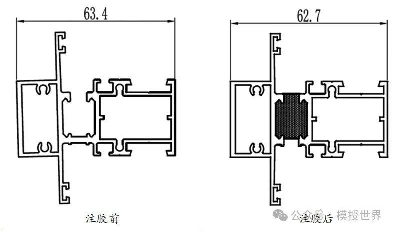
(3) Glue-injected profiles with certain structures will also have closing due to the shrinkage of the colloid after the glue is injected.
If the above-mentioned closing is not serious, it can be avoided by controlling the flow rate through mold design; but if several factors are superimposed and the mold design and related processes cannot solve the closing, pre-compensation can be given in the cross-section design, that is, pre-opening.
The amount of pre-opening compensation should be selected based on its specific structure and previous closing experience. At this time, the design of the mold opening drawing (pre-opening) and the finished drawing are different (Figure 1).
2.2 Split large-size sections into multiple small sections
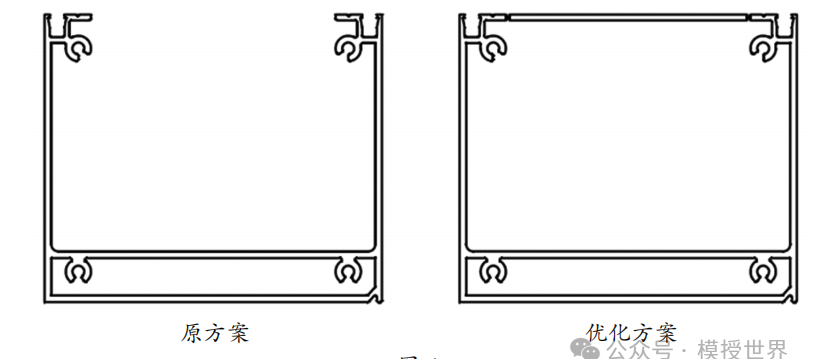
With the development of large-scale aluminum profiles, the cross-sectional designs of many profiles are getting larger and larger, which means that a series of equipment such as large extruders, large molds, large aluminum rods, etc. are needed to support them, and production costs rise sharply. For some large-size sections that can be achieved by splicing, they should be split into several small sections during design. This can not only reduce costs, but also make it easier to ensure flatness, curvature, and accuracy (Figure 2).
2.3 Set up reinforcing ribs to improve its flatness
Flatness requirements are often encountered when designing profile sections. Small-span profiles are easy to ensure flatness due to their high structural strength. Long-span profiles will sag due to their own gravity just after extrusion, and the part with the greatest bending stress in the middle will be the most concave. Also, because the wall panel is long, it is easy to generate waves, which will worsen the intermittency of the plane. Therefore, large-sized flat plate structures should be avoided in cross-section design. If necessary, reinforcing ribs can be installed in the middle to improve its flatness. (Figure 3)
2.4 Secondary processing
In the profile production process, some sections are difficult to complete by extrusion processing. Even if it can be done, the processing and production costs will be too high. At this time, other processing methods can be considered.
Case 1: Holes with a diameter less than 4mm on the profile section will make the mold insufficient in strength, easily damaged, and difficult to process. It is recommended to remove the small holes and use drilling instead.
Case 2: The production of ordinary U-shaped grooves is not difficult, but if the groove depth and groove width exceed 100mm, or the ratio of groove width to groove depth is unreasonable, problems such as insufficient mold strength and difficulty in ensuring the opening will also be encountered during production. When designing the profile section, the opening can be considered to be closed, so that the original solid mold with insufficient strength can be turned into a stable split mold, and there will be no problem of opening deformation during extrusion, making the shape easier to maintain. In addition, some details can be done at the connection between the two ends of the opening during design. For example: set V-shaped marks, small grooves, etc., so that they can be easily removed during final machining (Figure 4).
2.5 Complex on the outside but simple on the inside
Aluminum profile extrusion molds can be divided into solid molds and shunt molds according to whether the cross-section has a cavity. The processing of solid molds is relatively simple, while the processing of shunt molds involves relatively complex processes such as cavities and core heads. Therefore, full consideration must be given to the design of the profile section, that is, the outer contour of the section can be designed to be more complex, and grooves, screw holes, etc. should be placed on the periphery as much as possible, while the interior should be as simple as possible, and the accuracy requirements cannot be too high. In this way, both mold processing and maintenance will be much simpler, and the yield rate will also be improved.
2.6 Reserved margin
After extrusion, aluminum profiles have different surface treatment methods according to customer needs. Among them, anodizing and electrophoresis methods have little impact on the size due to the thin film layer. If the surface treatment method of powder coating is used, powder will easily accumulate in corners and grooves, and the thickness of a single layer can reach 100 μm. If this is an assembly position, such as a slider, it will mean that there are 4 layers of spray coating. Thickness up to 400 μm will make assembly impossible and affect use.
In addition, as the number of extrusions increases and the mold wears, the size of the profile slots will become smaller and smaller, while the size of the slider will become larger and larger, making assembly more difficult. Based on the above reasons, appropriate margins must be reserved according to specific conditions during design to ensure assembly.
2.7 Tolerance marking
For cross-section design, the assembly drawing is produced first and then the profile product drawing is produced. The correct assembly drawing does not mean that the profile product drawing is perfect. Some designers ignore the importance of dimension and tolerance marking. The marked positions are generally the dimensions that need to be guaranteed, such as: assembly position, opening, groove depth, groove width, etc., and are easy to measure and inspect. For general dimensional tolerances, the corresponding accuracy level can be selected according to the national standard. Some important assembly dimensions need to be marked with specific tolerance values in the drawing. If the tolerance is too large, assembly will be more difficult, and if the tolerance is too small, the production cost will increase. A reasonable tolerance range requires the designer’s daily experience accumulation.
2.8 Detailed adjustments
Details determine success or failure, and the same is true for profile cross-section design. Small changes can not only protect the mold and control the flow rate, but also improve the surface quality and increase the yield rate. One of the commonly used techniques is rounding corners. Extruded profiles cannot have absolutely sharp corners because the thin copper wires used in wire cutting also have diameters. However, the flow speed at the corners is slow, the friction is large, and the stress is concentrated, there are often situations where extrusion marks are obvious, the size is difficult to control, and molds are prone to chipping. Therefore, the rounding radius should be increased as much as possible without affecting its use.
Even if it is produced by a small extrusion machine, the wall thickness of the profile should not be less than 0.8mm, and the wall thickness of each part of the section should not differ by more than 4 times. During design, diagonal lines or arc transitions can be used at the sudden changes in wall thickness to ensure regular discharge shape and easy mold repair. In addition, thin-walled profiles have better elasticity, and the wall thickness of some gussets, battens, etc. can be about 1mm. There are many applications for adjusting details in design, such as adjusting angles, changing directions, shortening cantilevers, increasing gaps, improving symmetry, adjusting tolerances, etc. In short, profile cross-section design requires continuous summary and innovation, and fully considers the relationship with mold design, manufacturing, and production processes.
3. Conclusion
As a designer, in order to obtain the best economic benefits from profile production, all factors of the entire life cycle of the product must be considered during design, including user needs, design, manufacturing, quality, cost, etc., strive to achieve product development success the first time. These require daily tracking of product production and the collection and accumulation of first-hand information in order to predict the design results and correct them in advance.
Post time: Sep-10-2024


